
Gear Pump
Why choose us
Company strength
Our company covers an area of 26,000 square meters, with 5 CNC machining centers; 6 CNC lathes; 6 CNC milling machines; 5 CNC grinders; and 30 other CNC equipment.
Professional team
We have an excellent and experienced workforce capable of providing customers with high-quality products, professional technical consultation and comprehensive services.
Our certifications
Now it has more than 20 patents, passed ISO9000 certification, and its products have passed CE certification.
Advanced equipment
Our company has advanced production and testing equipment to provide you with the best products.
What is Gear Pump
Gear pump is a component in machine lubrication, oil supply or other liquid systems, and a type of hydraulic pump. It is of rotary type. There are two or more gears meshing in the gear box. Under the action of rotation, fluid is sucked in from one side and discharged to the other side. Its vibration and noise are slightly larger than those of screw pumps, so it can be used as a substitute for screw pumps. Its function is to make oil or other fluid media have a certain pressure, flow rate and flow direction.


Universal gear pump with the good fluid compatibility, is widely used in different industries,
And which shows excellent preformance except acidic, strong alkaline, and chloride fluid.
Specially for the isocyanate, polyether polyols, two components A and B, epoxy resin or sodium silicate
Benefits of Gear Pump
The gear pump is compact and consists of only two gears, the pump body and the front and rear covers. Therefore, compared with other pumps, the gear pump has a small weight, which is convenient for daily transportation and does not require much labor. It is also because of its light weight, the gear pump is more convenient to use, and it is more convenient when the work content is the same. At the same time, because of its simple structure and fewer components, it is more convenient to repair when problems are encountered.
Compared with the conventional pump, the gear pump is smaller in weight and easy to transport, which saves transportation costs to some extent. In addition, the gear pump is cheaper because of its simple structure and lower manufacturing cost. The maintenance procedure is simple in the future and the maintenance cost is low. Therefore, in general, gear pumps are more economical and can effectively save costs.
In fact, the fluid loss in the gear pump is small. Although some of the fluid is used to lubricate both sides of the bearing and gear, the pump body can never be fitted without clearance, resulting in a gear pump operating efficiency of 100%. However, the pump can still operate well and can achieve an efficiency of 93% to 98%.
If the viscosity or density of the fluid changes, the gear pump will not be affected too much. If a strainer or a restrictor is placed on the side of the discharge port, the gear pump will push the fluid through them. If the filter is dirty or clogged, the gear pump will still maintain a constant flow until it reaches the mechanical limit of the weakest part of the unit. This also causes the gear pump to be insensitive to oil contamination and is more suitable for use in petrochemical industries.
Application of Gear Pump
Hydraulic Systems
Gear pumps are commonly used in hydraulic systems for equipment such as forklifts, construction machinery, and industrial presses. They provide the required pressure to operate hydraulic cylinders and motors.
Automotive Industry
Gear pumps are used in automatic transmission systems, power steering systems, and engine lubrication systems in vehicles. They provide the necessary fluid pressure for these critical functions.
Chemical Processing
Gear pumps are employed in the chemical industry to transfer a wide range of fluids, including acids, solvents, and various chemicals. Their ability to handle viscous and abrasive materials makes them valuable for this application.
Oil and Gas Industry
Gear pumps are used for transferring crude oil, refined petroleum products, and drilling mud in the oil and gas industry. They are also employed in hydraulic fracturing (fracking) operations.
Food and Beverage Processing
Gear pumps are used for transferring and dosing food products like chocolate, syrups, and viscous sauces in the food processing industry.
Pharmaceutical Manufacturing
Gear pumps play a critical role in pharmaceutical manufacturing for the transfer of viscous and shear-sensitive materials, ensuring precise dosing and accurate blending.
Types of Gear Pump

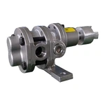
External Gear Pump
An external gear pump consists of two identical, interlocking gears supported by separate shafts. Generally, one gear is driven by a motor and this drives the other gear (the idler). In some cases, both shafts may be driven by motors.The shafts are supported by bearings on each side of the casing.No fluid is transferred back through the centre, between the gears, because they are interlocked. Close tolerances between the gears and the casing allow the pump to develop suction at the inlet and prevent fluid from leaking back from the discharge side (although leakage is more likely with low viscosity liquids).
Internal gear pump
An internal gear pump operates on the same principle but the two interlocking gears are of different sizes with one rotating inside the other.The larger gear (the rotor) is an internal gear i.e. it has the teeth projecting on the inside.Within this is a smaller external gear (the idler-only the rotor is driven) mounted off-centre.This is designed to interlock with the rotor such that the gear teeth engage at one point.A pinion and bushing attached to the pump casing holds the idler in position.A fixed crescent-shaped partition or spacer fills the void created by the off-centre mounting position of the idler and acts as a seal between the inlet and outlet ports.


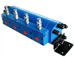
Multiple gear pumps
These pumps have multiple pairs of gears that operate simultaneously to achieve higher metering performance. They are often used in industrial applications where large volumes of liquid are required.
Gear pumps (gerotor pumps)
Gear pumps, also known as gerotor pumps, use an internal gear and an external gear with a special geometry. They offer a good combination of performance and compactness.

Pressure Relief Valve or Safety Valve
In order to prevent the pump from being damaged, this valve is installed on the outlet section so that it can release fluid in the event of excess pressure.
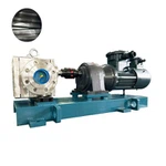
Prime Mover
The gear pump relies on a prime mover to drive the shaft that contains the power gear. It can be powered by manual labor, an IC engine, or an electric motor.
Driver or Power Gear
The driver or power gear is connected to the prime mover. This gear rotates with the power of the main motor.
Idler or Driven Gear
A driven gear meshes with a power gear. This gear rotates as the power gear does.
Inlet Section
This is the part of the pump that takes liquid into the pump. It is the inlet section that gets low-pressure liquid into the pump.
Outlet Section
In the after-sales service,we provide technical services such as installation as well as commissioning and maintenance.
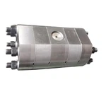
Housing
A hydraulic gear pump housing contains both the power gear and the idler gear.
How to Choose Gear Pump
External & Internal Gear Pumps
Both internal and external gear pumps have similar pumping principles, but there are some differences in design and construction. Fluid is trapped within the gear pump teeth and pushed to the high-pressure discharge side. The difference in pumping action is briefly explained in Image 1. Internal gear pumps typically have better suction capabilities than external gear designs and are suited to high viscosity fluids, although they have a useful operating range from 1 centipoise (cP) to over 1 million cP.
Clearances
As the fluid cannot seep back along the path it moved through, nor between the engaged gear teeth (they create a seal), it must exit through the outlet port. However, some gap/clearance is required between metal parts if they are rubbing against each other. Some fluid will seep through the side clearance of the gears to the casing, the peripheral clearance of the gear and bore in the casing and gear-to-gear clearance.
Pressure & Flow Rate
Flow rate is the amount of fluid being moved in unit time and pressure acts as energy to move that fluid against frictional resistance and gravity. Pressure and flow are two of the primary parameters that indicate the right selection of the pump and necessary modifications.Unlike centrifugal pumps, in gear pumps or any other positive displacement pumps, flow rate is directly proportional to pump speed. Each revolution will deliver a fixed amount of fluid.
Viscosity
As already noted, gear pumps often are chosen to pump high viscous fluid. It is important to understand what changes are needed to make inside a pump as we go higher in viscosity level.
Liquid Temperature
Liquid viscosity decreases with an increase in temperature. Liquids are often heated prior to pumping for higher allowable speeds, greater capacities and lower power requirements. Conversely, pumps are often required to handle low temperature liquids, particularly in refrigeration or air conditioning equipment. In either case, special consideration must be given to pump construction at extreme temperature conditions. High temperature may require special gaskets, packing materials and varying amounts of added clearances applied to the internal parts of the pump to avoid scoring, galling and other mechanical failures.
Materials of Construction
In selecting the materials of construction, factors that must be considered—other than consideration of the liquid itself—are temperature, contamination and concentration of the liquid. The initial cost of materials, replacement costs and longevity of service should also be considered. Standard pump part materials like cast iron, bronze and low-carbon steel are typically less expensive initially. However, these materials can become more expensive if they cause premature failure, unexpected service and replacement. Often, 300 and 400 series stainless steel are popular for corrosion-abrasion conditions.
How Does a Gear Pump Work?
This cycle of inlet, metering, conveying, and outlet is repeated continuously to provide the desired amount of material to be dispensed. The speed and metering amount can be precisely adjusted by controlling the speed of rotation of the gears.It is important to note that accurate metering in gear pumps depends on the precision of the gears and the control of the rotational speed. Gear pumps offer the advantage of relatively constant and low-pulsation metering, which is beneficial in many metering applications.
Gear pumps are used in a variety of industries, including chemical, food processing, oil and gas, pharmaceutical manufacturing and many others where precise metering of liquids or viscous materials is required.
Inlet Phase
At the beginning of the pumping cycle, both gears are in close contact with each other and the pump chamber is filled with the material to be pumped. The inlet valve is open and the material is fed to the pump through a feeding system.
Metering phase
As the gears rotate, the gaps between the teeth on the material inlet side each fill with material. On the material outlet side, the material is displaced from the pump via the engagement of the teeth of one gear in each case in the tooth gaps of the other gear, and is thus conveyed.
Conveying phase
As the gears continue to rotate, the displaced material is conveyed into the metering area toward the outlet. The outlet valve opens and the material is discharged from the pump into the metering system or metering point.
Gear Pump Operation
Operate close to the maximum rated speeds
Because gear pumps have poor volumetric efficiency at low speeds and low flow rates, they should be operated as close as possible to their maximum rated speeds for higher production and efficiency.
Use special materials when pumping liquids with abrasives
A pump’s toothed gear construction allows particles to become trapped in small spaces, accelerating wear and reducing efficiency. If you need to transfer fluid containing abrasives, consider contacting the pump manufacturer to discuss hardened material options.
Ensure that total life does not exceed 7.5 PSI
A gear pump cannot create a perfect vacuum, necessitating total lift (including pipe friction losses) to be one-half of the atmospheric pressure (approximately 7.5 PSI).
Avoid low viscosity fluids
Gear pumps (especially internal gear pumps) are designed to handle high viscosity fluids to minimize slip. Pumping low viscosity fluids results in reduced flow rate and efficiency because it ‘slips’ through the tight spaces from the higher-pressure discharge side of the pump to the lower-pressure suction side of the pump.
Do not run dry
Unlubricated gear teeth will rub together, creating friction and heat as the cogs expand and begin rubbing against the housing. This can destroy the pump, requiring costly repair and downtime
How to Maintain Gear Pump
Keep maintenance records
One of the most important things you can do to ensure your pump operates smoothly is to keep a detailed record of baseline pump performance, regular maintenance, and any repairs. This will aid you in determining how the pump will operate in the future and the best way to either repair or replace specific parts.
Check bearings regularly
The bearings are the most important area to maintain because they can cause imbalance if misplaced or defective. Check bearings regularly and replace as necessary by removing the defective bearing with a puller. Excessive noise can be an indication of bearing wear.
Check gear pump clearance
A new gear pump has .007 to .005 inches of clearance from both the teeth and chamber of the gears. Periodically check for wearing of the teeth by attempting to pass a piece of paper between the clearances. If it passes between the clearances easily, it indicates that the bearings have been worn down and should be replaced.

Our Factory
Jinan Hai Rui Te Mechanical CO., LTD was founded in 2005. Our talented and experienced staff can provide products with good quality, professional technical consult, and perfect service to our clients. "Keep improving " is a principle we always insist. More than sixty percent of the company staff have bachelor or higher university degrees. Now We have more than 20 patents, passed ISO9000 certification, and our products have passed CE certification. As a professinal fluid service provider, we only manufacture and sell quality products. Clients can rest assured our products and services will solve all their fluid metering problems efficiently and economically.
Certificate


